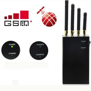
What are jammers?
Commonly referred to as signal blockers, devices used to block and jam radio communication signals
What are the civil (commercial) bumblebees?
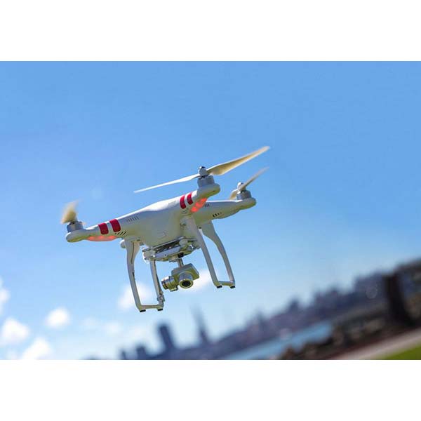
Also note that unmanned aerial vehicles (UAVs) are human unmanned aircraft on board. The flight is controlled by the remote control of a pilot on the ground. The typical method of starting and recovering a remotely controlled aircraft is through the function of an automated system or an external operator on the ground. There are a variety of shapes, sizes, configurations, and characteristics of bumblebees.
Why a civil drone jammer?
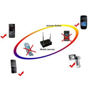
Commercial bumblebees have raised privacy concerns with US residents as most bumblebees are equipped with high quality cameras that can invade people’s privacy and take pictures of people and personal property. Bumblebees can also be used to smuggle drugs, smuggle into buildings, act as peep toms, drop bombs, shoot guns, and collect personal information on anyone the drone pilot is trying to harm. Hence, a drone jammer is required to block the signal from the remote controlled drone to protect our privacy and personal space.
Jammer legalization
The jammer that blocks GPS, cellular and / or WIFI is illegal in some countries. Therefore, this jammer is for educational purposes only, and not for commercial or personal use.
The design
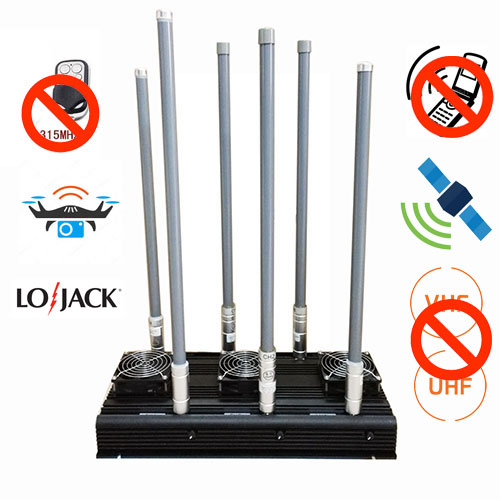
What to BLOCK?
In this design we are blocking the most commonly used R / C remote control connection from the commercial bumblebee manufacturer (such as Parrot AR Bumblebees). Common R / C frequencies: Band 1: 2.4 MHz – WIFI g / b / n: ≈ 2.4 – 2.5 gigahertz band 2: 433 MHz ISM band: 433.05-434.79 MHz
Design overview
The design includes two band jammers (i.e. Band 1 and Band 2). The RF circuit consists of the voltage controlled oscillator to scan the tape required with the tuning circuit to drive the VCO and includes a linear power amplifier to amplify the output power of the VCO. The tuning circuit mainly consists of sawing the tooth generator to generate the tuning signal with the noise generator to tune the VCO to the required RF blocking the signal. Last but not least, the power supply circuit is designed in such a way that it supplies the DC voltages required for the HF and the tuning circuit alternately with 220/110.
RF power supply
The maximum power of the ISM bands permitted for civil drones is 36 dBm EIRP (effective isotropic radiation power) with a maximum transmission power of 1 W (30 dBm) and a minimum signal-to-noise ratio SNR of DB 4 data. Use simple arithmetic; The radiated power of the HF jammer must be more than 32 dBm EIRP.
To achieve this required radiated power for 1 RF band switching, the power amplifier cascaded with the overall gain of the DB 30 by two is used with the antenna VCO of the output power and 7 dBi of 3 dBm; The radiated power of the band 1 RF circuit is 40 dBm, which exceeds the blocking power required to block the R / C communications of the “Band 1 (2.4 GHz)” drone.
For the band 2 circuit (433 megahertz) rf; A high gain power amplifier is used with a typical gain of 35 dB and a dBi 2 antenna is used which radiates a total EIRP power of 37 dBm, which is more than the blocking power required to block the civilian Bourdon R communication is required / C “of band 2 (433 megahertz).
Device parts
Assemble the main parts of an RF circuit using 1 jammer (2.4GHz): the following parts are the main parts, the rest can be found in the construction drawings.
Linear Power Amplifier: Two RFMD RF2317 CATV linear amplifiers
Voltage Controlled Oscillator (VCO)
CRYSTEKCVCO33BE-2400-2500 VCO, which covers the frequencies from 2400 to 2500 megahertz of the voltage tuning input for VCO, is 0 VDC to 3 VDC, dBm output power 3 to 3 impedances of continuous voltage and output of 50 ohms, which corresponds to the input impedance of the power amplifier
ANTENNA
7dbi 2.4 GHz rubber antenna
Assemble 2 main parts of the jammer circuit (433 MHz) RF: the following are the main parts, the rest can be found in the construction drawings.
Linear power amplifier: Skyworks SKY65116: 390-500 megahertz power amplifier. With internal matched impedance at 50 ohms
Voltage Controlled Oscillator (VCO): CRYSTEKCVCO33BE-2400-2500 VCO, which covers the frequencies from 2400 to 2500 megahertz for the voltage tuning input for the VCO, is 0 VDC to 3 VDC, output power from dBm 3 to 3 impedances DC and 50 ohm output, the corresponds to the input impedance of the power amplifier
ANTENNA: 1/4 wave whip, SMA- right angle, 433 MHz
Parts of the main circuits: The following parts are the main parts, the rest can be found in the construction drawings.
Timer 555: To create space that is converted to triangular air, the VCO welcomes
Zener diode with ampere power: For generating a signal with white noise